SOLIDWORKS Macro - Create Linear Pattern
Objective of this article is to learn how to create Linear pattern feature through SOLIDWORKS VBA Macros in SOLIDWORKS.
We create Linear pattern Feature in following steps in general.
- Ask user to select a Feature to Linear pattern.
- Ask user to select an edge for Linear pattern in direction 1.
- Ask user to select an edge for Linear pattern in direction 2.
- Create Linear pattern feature data.
- Create Linear pattern feature.
This method is most updated method, so use this method if you want to create a new Linear pattern Feature quickly.
Results We Can Get
After running our macro we successfully create Linear pattern feature as a result.
Below image shows the result we get.
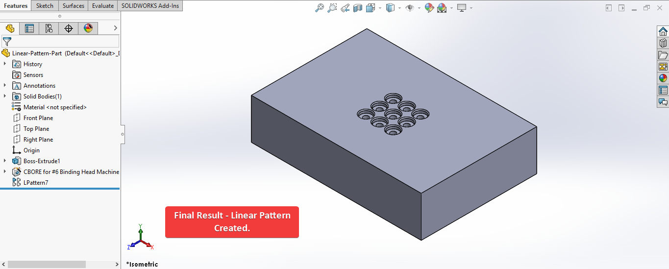
To get the correct result please follow the steps correctly.
Video of Code on YouTube
Please see below 🎬 video on how to create Linear pattern feature from SOLIDWORKS VBA Macros.
How to Create Linear Pattern Feature
Please note that there are no explanations in the video.
Explanation of each step and why we write code this way is provided in this post.
Code Sample
Below is the code for creating Linear pattern Feature feature in VBA is given.
Option Explicit

' Variable for Solidworks Application
Dim swApp As SldWorks.SldWorks

' Variable for Solidworks document
Dim swDoc As SldWorks.ModelDoc2

' Variable for Solidworks Linear pattern Feature
Dim swFeature As SldWorks.Feature

' Variable for Solidworks Selection Manager
Dim swSelMgr As SldWorks.SelectionMgr

' Variable for Solidworks Entity
Dim swObject As SldWorks.Entity

' Variable for Solidworks Select Data
Dim swSelData As SldWorks.SelectData

' Variable for Linear pattern feature data
Dim swLinearPatternFeatureData As SldWorks.LinearPatternFeatureData

' Main program for Linear pattern
Sub main()

  ' Set Solidworks Application variable to current application
  Set swApp = Application.SldWorks

  ' Check if Solidworks is opened or not
  If swApp Is Nothing Then
    MsgBox ("Solidworks is not opened")
    Exit Sub
  End If

  ' Set Solidworks document variable to currently opened document
  Set swDoc = swApp.ActiveDoc

  ' Check if Solidworks document is opened or not
  If swDoc Is Nothing Then
    MsgBox ("Solidworks document is not opened. Please open a document.")
    Exit Sub
  End If

  ' Set Solidworks Selection Manager variable
  Set swSelMgr = swDoc.SelectionManager

  ' Array of Solidworks Entities
  Dim swObjects(1 To 3) As SldWorks.Entity

  ' Local variable for selection
  Dim selectItems As Integer
  selectItems = 1

  ' Loop till we select all entities
  While selectItems <= 3

    ' Message to show user
    Dim messageToUser As String

    ' Update Messages
    Select Case selectItems
      Case 1
         messageToUser = "Please select a Feature for Linear Pattern."
      Case 2
         messageToUser = "Please select first Edge for Direction 1."
      Case 3
         messageToUser = "Please select second Edge for Direction 2."
      Case Else
         Exit Sub
    End Select

    ' Show message to user
    MsgBox messageToUser

    ' Loop until Solidworks Entity variable is equal to selected edge
    While swObjects(selectItems) Is Nothing

      ' Local integer for loop
      Dim i As Integer

      ' Looping until we select
      For i = 1 To swSelMgr.GetSelectedObjectCount2(-1)

          ' Update Selection
          Select Case selectItems
            Case 1
              ' If the selection type body feature
              If swSelMgr.GetSelectedObjectType3(i, -1) = swSelectType_e.swSelBODYFEATURES Then

                ' Set the Solidworks Entity object to feature for Linear pattern
                Set swObjects(selectItems) = swSelMgr.GetSelectedObject6(i, -1)

              ' If the face is selected
              ElseIf swSelMgr.GetSelectedObjectType3(i, -1) = swSelectType_e.swSelFACES Then

                ' Inform user to select feature from Feature Tree
                MsgBox "Please select Feature from Feature Tree."

                ' Clear selection
                swDoc.ClearSelection2 True
              End If
            Case 2, 3
              ' If the edge is selected
              If swSelMgr.GetSelectedObjectType3(i, -1) = swSelectType_e.swSelEDGES Then

                ' Set the Solidworks Entity object to selected edge
                Set swObjects(selectItems) = swSelMgr.GetSelectedObject6(i, -1)
              Else
                ' Inform user to select edge
                MsgBox "Please select an Edge."

                ' Clear selection
                swDoc.ClearSelection2 True
              End If
          End Select
      Next

      DoEvents
    Wend

    ' Clear previous selection
    swDoc.ClearSelection2 True

    ' Increase the selection count
    selectItems = selectItems + 1

  Wend

  ' Clear previous selection
  swDoc.ClearSelection2 True

  ' Local variable for counter
  Dim j As Integer
  j = 1

  ' Loop till counter is 3, since we have 3 selection
  While j < 4

    ' Set the current instance to Solidworks Entity variable
    Set swObject = swObjects(j)

    ' Create Select data for this entity
    Set swSelData = swSelMgr.CreateSelectData

    ' Update Marking as per selected entity
    Select Case j
      Case 1
        ' For feature to pattern, set mark to 4
        swSelData.Mark = 4
      Case 2
        ' For direction 1, set mark to 1
        swSelData.Mark = 1
      Case 3
        ' For direction 1, set mark to 2
        swSelData.Mark = 2
    End Select

    ' Select the current entity
    swObject.Select4 True, swSelData

    j = j + 1

  Wend

  '-----------------------BELOW IS THE SOLUTION----------------------------------------

  ' Local variables used as Conversion Factors
  Dim LengthConversionFactor As Double
  Dim AngleConversionFactor As Double

  ' Use a Select Case, to get the length of active Unit and set the different factors
  Select Case swDoc.GetUnits(0)       ' GetUnits function gives us, active unit

    Case swMETER    ' If length is in Meter
      LengthConversionFactor = 1
      AngleConversionFactor = 1

    Case swMM       ' If length is in MM
      LengthConversionFactor = 1 / 1000
      AngleConversionFactor = 1 * 0.01745329

    Case swCM       ' If length is in CM
      LengthConversionFactor = 1 / 100
      AngleConversionFactor = 1 * 0.01745329

    Case swINCHES   ' If length is in INCHES
      LengthConversionFactor = 1 * 0.0254
      AngleConversionFactor = 1 * 0.01745329

    Case swFEET     ' If length is in FEET
      LengthConversionFactor = 1 * (0.0254 * 12)
      AngleConversionFactor = 1 * 0.01745329

    Case swFEETINCHES     ' If length is in FEET & INCHES
      LengthConversionFactor = 1 * 0.0254  ' For length we use sama as Inch
      AngleConversionFactor = 1 * 0.01745329

    Case swANGSTROM        ' If length is in ANGSTROM
      LengthConversionFactor = 1 / 10000000000#
      AngleConversionFactor = 1 * 0.01745329

    Case swNANOMETER       ' If length is in NANOMETER
      LengthConversionFactor = 1 / 1000000000
      AngleConversionFactor = 1 * 0.01745329

    Case swMICRON       ' If length is in MICRON
      LengthConversionFactor = 1 / 1000000
      AngleConversionFactor = 1 * 0.01745329
  End Select

  '----------------------------------------------------------------

  'Create linear pattern feature data
  Set swLinearPatternFeatureData = swDoc.FeatureManager.CreateDefinition(swFmLPattern)

  ' Set Linear pattern feature data values
  swLinearPatternFeatureData.D1EndCondition = swPatternEndCondition_e.swPatternEndCondition_SpacingAndInstances
  swLinearPatternFeatureData.D1ReverseDirection = False
  swLinearPatternFeatureData.D1Spacing = InputBox("Please select spacing in direction 1") * LengthConversionFactor
  swLinearPatternFeatureData.D1TotalInstances = InputBox("Number of instances in direction 1")
  swLinearPatternFeatureData.D2EndCondition = swPatternEndCondition_e.swPatternEndCondition_SpacingAndInstances
  swLinearPatternFeatureData.D2PatternSeedOnly = False
  swLinearPatternFeatureData.D2ReverseDirection = False
  swLinearPatternFeatureData.D2Spacing = InputBox("Please select spacing in direction 2") * LengthConversionFactor
  swLinearPatternFeatureData.D2TotalInstances = InputBox("Number of instances in direction 2")
  swLinearPatternFeatureData.GeometryPattern = False
  swLinearPatternFeatureData.VarySketch = False

  ' Create Linear pattern
  Set swFeature = swDoc.FeatureManager.CreateFeature(swLinearPatternFeatureData)

  ' Check if Linear Pattern creates or not
  If swFeature Is Nothing Then
    MsgBox ("Failed to create Linear Pattern.")
    Exit Sub
  End If

  ' Erase array data
  Erase swObjects

  ' View zoom to fit
  swDoc.ViewZoomtofit2

  ' Clear all selection
  swDoc.ClearSelection2 True

End Sub
Prerequisite
There are some prerequisite for this article.
We are not creating feature from code but we use existing Extrude feature and Hole feature to create Linear pattern feature as shown in below picture.
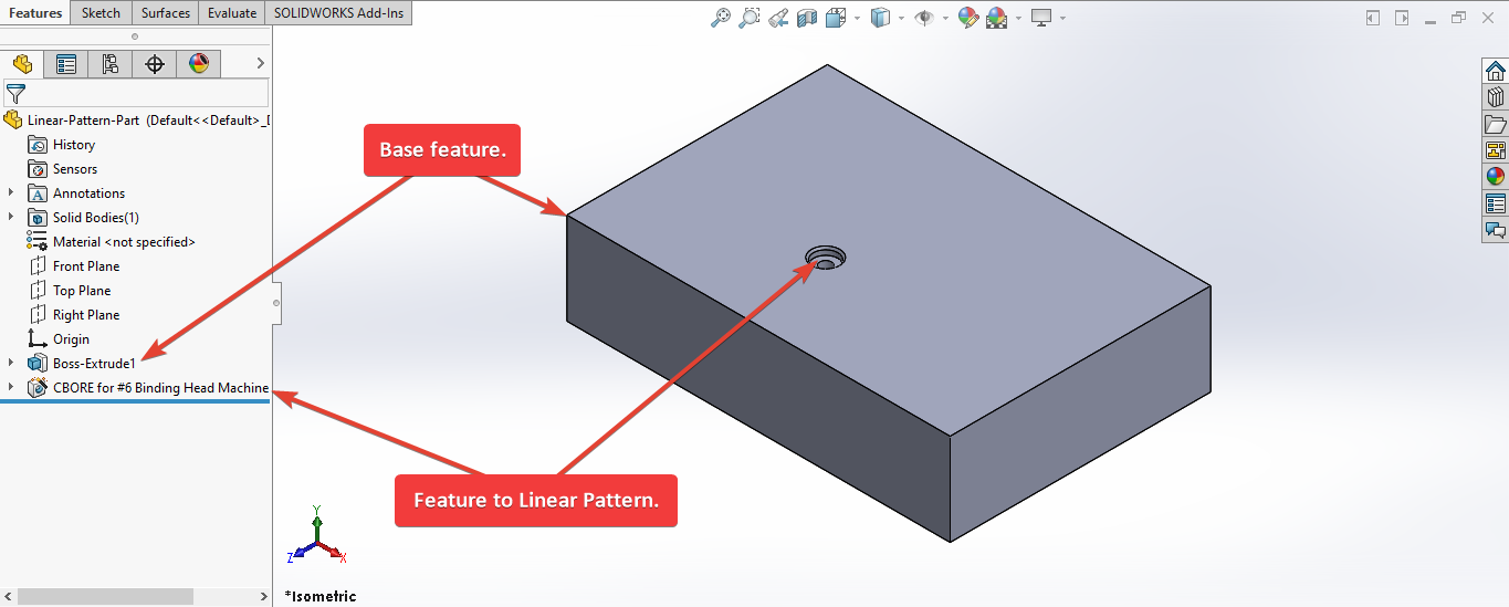
As shown in above image, there are 1 Extrude and 1 Hole feature in our part.
Extrude Feature: This is our Extruded feature.Hole Feature: This is our Hole feature for Linear pattern.
If you want to create Extrude feature programmatically then please refer to below article.
If you want to create Hole feature programmatically then please refer to below article.
We will apply checks in this article, so the code we write should be error free most of the time.
Steps To Follow
To create Linear pattern Feature there are following steps:
- Creating Global Variables
- Initializing required variables
- Ask user to select feature and directions
- Mark selected entities
- Get unit Conversion factors
- Create Linear Pattern feature using Linear Pattern feature definition .
- Final work
Now let us walk through each step as given above, and understand every line.
I also give some links so that you can go through them if there are anything I explained in previous articles.
Creating Global Variables
Option Explicit
This line forces us to define every variable we are going to use.
For more information please visit SOLIDWORKS Macros - Open new Part document post.
We create following variables.
- Variable for Solidworks application
' Variable for Solidworks application
Dim swApp As SldWorks.SldWorks
In this line, we create a variable which we named as swApp and the type of this swApp variable is SldWorks.SldWorks.
To see methods and properties related to SldWorks.SldWorks object, please visit
this page of SOLIDWORKS API Help
.
- Variable for Solidworks document
' Variable for Solidworks document
Dim swDoc As SldWorks.ModelDoc2
In this line, we create a variable which we named as swDoc and the type of this swDoc variable is SldWorks.ModelDoc2.
To see methods and properties related to SldWorks.ModelDoc2 object, please visit
this page of SOLIDWORKS API Help
.
- Variable for Solidworks Linear pattern Feature
' Variable for Solidworks Linear pattern Feature
Dim swFeature As SldWorks.Feature
In this line, we Create a variable which we named as swFeature and the type of this swFeature variable is SldWorks.Feature.
We create variable swFeature for SOLIDWORKS Linear pattern Feature.
To see methods and properties related to Feature object, please visit
this page of SOLIDWORKS API Help
.
- Variable for Solidworks Selection Manager
' Variable for Solidworks Selection Manager
Dim swSelMgr As SldWorks.SelectionMgr
In this line, we create a variable which we named as swSelMgr and the type of this swSelMgr variable is SldWorks.SelectionMgr.
To see methods and properties related to SldWorks.SelectionMgr object, please visit
this page of SOLIDWORKS API Help
.
- Variable for Solidworks Entity
' Variable for Solidworks Entity
Dim swObject As SldWorks.Entity
In this line, we Create a variable which we named as swObject and the type of this swObject variable is SldWorks.Entity.
We create variable swObject for SOLIDWORKS Entities (Profile and Path) we ask use to select.
To see methods and properties related to SldWorks.Entity object, please visit
this page of SOLIDWORKS API Help
.
- Variable for Solidworks Select Data
' Variable for Solidworks Select Data
Dim swSelData As SldWorks.SelectData
In this line, we create a variable named swSelData as SldWorks.SelectData object type.
We create variable swSelData for SOLIDWORKS Select Data, which we use for Marking selected object.
To see methods and properties related to SldWorks.SelectData object, please visit
this page of SOLIDWORKS API Help
.
- Variable for Solidworks Thread feature data
' Variable for Linear pattern feature data
Dim swLinearPatternFeatureData As SldWorks.LinearPatternFeatureData
In this line, we create a variable which we named as swThreadFeatData and the type of this swThreadFeatData variable is SldWorks.ThreadFeatureData.
To see methods and properties related to SldWorks.ThreadFeatureData object, please visit
this page of SOLIDWORKS API Help
.
These all are our global variables.
They are SOLIDWORKS API Objects.
So basically I group all the SOLIDWORKS API Objects in one place.
' Main program for Linear pattern
Sub main()

End Sub
Next is our Sub procedure which has name of main.
This procedure hold all the statements (instructions) we give to computer.
To know more about Sub Procedure you can check VBA Sub and Function Procedures article of this website.
Initializing Required Variables
Inside this procedure we first initialize required variables as given below.
- Set SOLIDWORKS variable to SOLIDWORKS application
' Set SOLIDWORKS variable to SOLIDWORKS application
Set swApp = Application.SldWorks
In this line, we set the value of our SOLIDWORKS variable swApp; which we define earlier; to SOLIDWORKS application.
' Check if SOLIDWORKS is opened or not
If swApp Is Nothing Then
  MsgBox ("SOLIDWORKS is not opened")
  Exit Sub
End If
In above line of code, we use an IF statement to check if SOLIDWORKS application variable is successfully assigned to current SOLIDWORKS application.
- Set SOLIDWORKS document variable to opened part document
' Set SOLIDWORKS document variable to opened part document
Set swDoc = swApp.ActiveDoc
In above line of code, we set SOLIDWORKS document swDoc variable to currently open part document.
' Check if SOLIDWORKS document is opened or not
If swDoc Is Nothing Then
  MsgBox ("SOLIDWORKS document is not opened. Please open a document.")
  Exit Sub
End If
If SOLIDWORKS document is not opened then code execute inside the code and inform the user by a Message Window .
- Set SOLIDWORKS Selection Manager variable
' Set SOLIDWORKS Selection Manager variable
Set swSelMgr = swDoc.SelectionManager
In above line, we set SOLIDWORKS Selection ManagerswSelMgr variable to current document’s Selection Manager.
- Array of SOLIDWORKS Entities
' Array of Solidworks Entities
Dim swObjects(1 To 3) As SldWorks.Entity
In this line, we create an Array of SOLIDWORKS Entities which we named as swObjects and the type of this SldWorks.Entity variable is SldWorks.Entity.
This array consist two SldWorks.Entity variables.
We define the number of variable this array holds inside (1 To 3).
For more information about the Arrays in VBA please Array on this website .
- Local variable for User selection
' Local variable for selection
Dim selectItems As Integer
selectItems = 1
In above line of code, we define a Local variable name selectItemsas Integer type.
In next line we assign a value of 1.
—### Ask user to select feature and directions
Now we will ask user to select feature and directions for Linear Pattern feature.
Please follow steps given below.
' Loop till we select all entities
While selectItems <= 3

Wend
In above line of code we start a While loop.
For more details about While loop, please see
VBA Looping
article from this website.
We want to loop until selectItems variable’s value is equal to 3.
' Message to show user
Dim messageToUser As String
In above line of code we create a variable named messageToUser of String type.
This variable holds the message we want to show before selection.
' Update Messages
Select Case selectItems
  Case 1
    messageToUser = "Please select a Feature for Linear Pattern."
  Case 2
    messageToUser = "Please select first Edge for Direction 1."
  Case 3
    messageToUser = "Please select second Edge for Direction 2."
  Case Else
    Exit Sub
End Select
In above line of code, we use a Select statement to update message.
We use the case on selectItems.
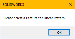
When selectItems = 1 then value of messageToUser update to "Please select a Feature for Linear Pattern."
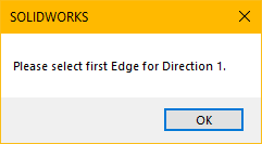
When selectItems = 2 then value of messageToUser update to "Please select first Edge for Direction 1."
Similarly, when selectItems = 3 then value of messageToUser upda te to "Please select second Edge for Direction 2."
' Show message to user
MsgBox messageToUser
In above line of code, we show the message to user.
Below image shows the message for Feature selection to the user.
Below image shows the message for first Edge for Direction 1 to the user.
Below image shows the message for second Edge for Direction 2 to the user.
' Loop until we complete our selection
While swObjects(selectItems) Is Nothing

Wend
In above line of code, we create another While loop.
This loops until we select the our Profile and Path.
For more details about While loop, please see
VBA Looping
article from this website.
' Local integer for loop
Dim i As Integer
In above line of code, we create a local integer name i as a counter.
' Loop until we select
For i = 1 To swSelMgr.GetSelectedObjectCount2(-1)

Next
In above line of code, we create a For loop.
This code loops from i = 1 to number of objects we select.
' Update Messages
Select Case selectItems

End Select
In above line of code, we use a Select statement for selection entities.
We use the case on selectItems.
Case 1
	' If the profile sketch is selected
  If swSelMgr.GetSelectedObjectType3(i, -1) = swSelectType_e.swSelBODYFEATURES Then

    ' Set the Solidworks Entity object to feature for Linear pattern
    Set swObjects(selectItems) = swSelMgr.GetSelectedObject6(i, -1)

    ' If the face is selected
  ElseIf swSelMgr.GetSelectedObjectType3(i, -1) = swSelectType_e.swSelFACES Then

    ' Inform user to select feature from Feature Tree
    MsgBox "Please select Feature from Feature Tree."

    ' Clear selection
    swDoc.ClearSelection2 True
  End If
Above code sample we use for Case 1.
In above line of code, we use IF/Else statement with conditions.
The
IF statement
is True when selected object is type of SOLIDWORKS Body Feature.
Similarly,
Else statement
is True when select object is type of SOLIDWORKS Face.
When we select the sketch from Model view, then selected object is SOLIDWORKS Face. When we select the sketch from Feature Tree, then select object is SOLIDWORKS Body Feature.
When IF statement is True we execute code given below.
' Set the Solidworks Entity object to feature for Linear pattern
Set swObjects(selectItems) = swSelMgr.GetSelectedObject6(i, -1)
In above line, we set the indexed object inside array.
- Array of SOLIDWORKS Entities =
swObjects - Indexed Entity Object =
swObjects[selectItems]
We set the value of this Indexed Entity Object by GetSelectedObject6() method of SOLIDWORKS Selection Manager.
When we set the Indexed Entity Object value as feature to mirror, we exit the 2nd While loop.
Similarly, when Else statement is True we execute code given below.
' Inform user to select feature from Feature Tree
MsgBox "Please select feature from Feature Tree."

' Clear selection
swDoc.ClearSelection2 True
- We show message to user to select Feature from Feature Tree.
- After that we clear our selection.
We do this because if selected object type is SOLIDWORKS Face then we can not assign this object as SOLIDWORKS Entity inside array.
Case 2, 3
  ' If the edge is selected
  If swSelMgr.GetSelectedObjectType3(i, -1) = swSelectType_e.swSelEDGES Then

    ' Set the Solidworks Entity object to selected edge
    Set swObjects(selectItems) = swSelMgr.GetSelectedObject6(i, -1)

  Else
    ' Inform user to select edge
    MsgBox "Please select a Edge."

    ' Clear selection
    swDoc.ClearSelection2 True
  End If
Above code sample we use for Case 2 and Case 3.
In above line of code, we use IF/Else statement with conditions.
The
IF statement
is True when selected object is type of SOLIDWORKS Edge.
If we the selected object is not type of SOLIDWORKS Edge then
Else statement
code runs.
When IF statement is True we execute code given below.
' Set the Solidworks Entity object to selected Edge
Set swObjects(selectItems) = swSelMgr.GetSelectedObject6(i, -1)
In above line, we set the indexed object inside array.
- Array of SOLIDWORKS Entities =
swObjects - Indexed Entity Object =
swObjects[selectItems]
We set the value of this Indexed Entity Object by GetSelectedObject6() method of SOLIDWORKS Selection Manager.
When we set the Indexed Entity Object value as feature to mirror, we exit the 2nd While loop.
Similarly, when Else statement is True we execute code given below.
' Inform user to select edge
MsgBox "Please select a Edge."

' Clear selection
swDoc.ClearSelection2 True
- We show message to user to select Edge.
- After that we clear our selection.
After For loop, we have a call for DoEvents function.
This function repeats the While loop until we select the Feature or Edge.
' Clear previous selection
swDoc.ClearSelection2 True

' Increase the selection count
selectItems = selectItems + 1
In above line, when we finished with the Profile or Path selection, we clear previous selection and increment the selected count by 1.
After increment the selected count we continue our while loop.
Mark selected Entities
Till now we have completed our selection.
Now we need to do Select and Mark entities correctly from our Array.
' Local variable for counter
Dim j As Integer
j = 1
In above line of code we create integer variable for counter.
' Loop till counter is 3, since we have 3 selection
While j < 4

Wend
In above line of code we create a while loop with condition that counter value of j should be less than 4.
' Set the current instance to Solidworks Entity variable
Set swObject = swObjects(j)
In above line of code, we set the SOLIDWORKS Entity variable to current object from array.
' Create Select data for this entity
Set swSelData = swSelMgr.CreateSelectData
In above line of code, we create SOLIDWORKS Select Data for current SOLIDWORKS Entity object.
' Update Messages
Select Case j

End Select
In above line of code, we use a Select statement for selection entities.
We use the case on j.
Case 1
  ' For feature to pattern, set mark to 4
  swSelData.Mark = 4
Above code sample we use for Case 1.
In above lines, we update the Mark to 4 for our SOLIDWORKS Select Data variable.
| Any... | Must be preselected and marked with a value of... |
|---|---|
| Direction 1 | 1 |
| Direction 2 | 2 |
| Feature to pattern | 4 |
For more details about Mark please visit Linear Pattern Feature in SOLIDWORS API Help.
Case 2
  ' For direction 1, set mark to 1
  swSelData.Mark = 1
Above code sample we use for Case 2.
In above lines, we update the Mark to 1 for our SOLIDWORKS Select Data variable.
| Any... | Must be preselected and marked with a value of... |
|---|---|
| Direction 1 | 1 |
| Direction 2 | 2 |
| Feature to pattern | 4 |
For more details about Mark please visit Linear Pattern Feature in SOLIDWORS API Help.
Case 3
  ' For plane, set mark to 2
  swSelData.Mark = 2
Above code sample we use for Case 3.
In above lines, we update the Mark to 3 for our SOLIDWORKS Select Data variable.
| Any... | Must be preselected and marked with a value of... |
|---|---|
| Direction 1 | 1 |
| Direction 2 | 2 |
| Feature to pattern | 4 |
For more details about Mark please visit Linear Pattern Feature in SOLIDWORS API Help.
' Select the current entity
swObject.Select4 True, swSelData
In above line of code, we select the Feature object.
We select it by using Select4 method of SOLIDWORKS Entity object.
This method takes 2 arguments.
- Append -
Trueappends the entity to the selection list,Falsereplaces the selection list with this entity. - Data - Pointer to the
ISelectDataobject.
We use following values as parameter.
- Append -
True - Data -
swSelData
j = j + 1
After Select statement, we increment the counter variable j by 1.
Get unit Conversion factors
Now we need to get unit Conversion factors as shown in below code.
'-----------------------Unit Conversion Factors----------------------------------------

' Local variables used as Conversion Factors
Dim LengthConversionFactor As Double
Dim AngleConversionFactor As Double

' Use a Select Case, to get the length of active Unit and set the different factors
Select Case swDoc.GetUnits(0)       ' GetUnits function gives us, active unit

Case swMETER    ' If length is in Meter
  LengthConversionFactor = 1
  AngleConversionFactor = 1

Case swMM       ' If length is in MM
  LengthConversionFactor = 1 / 1000
  AngleConversionFactor = 1 * 0.01745329

Case swCM       ' If length is in CM
  LengthConversionFactor = 1 / 100
  AngleConversionFactor = 1 * 0.01745329

Case swINCHES   ' If length is in INCHES
  LengthConversionFactor = 1 * 0.0254
  AngleConversionFactor = 1 * 0.01745329

Case swFEET     ' If length is in FEET
  LengthConversionFactor = 1 * (0.0254 * 12)
  AngleConversionFactor = 1 * 0.01745329

Case swFEETINCHES     ' If length is in FEET & INCHES
  LengthConversionFactor = 1 * 0.0254  ' For length we use sama as Inch
  AngleConversionFactor = 1 * 0.01745329

Case swANGSTROM        ' If length is in ANGSTROM
  LengthConversionFactor = 1 / 10000000000#
  AngleConversionFactor = 1 * 0.01745329

Case swNANOMETER       ' If length is in NANOMETER
  LengthConversionFactor = 1 / 1000000000
  AngleConversionFactor = 1 * 0.01745329

Case swMICRON       ' If length is in MICRON
  LengthConversionFactor = 1 / 1000000
  AngleConversionFactor = 1 * 0.01745329
End Select

'----------------------------------------------------------------
I have already explained about this in previous Solidworks Macro - Fix Unit Issue article in this website.
Please visit Solidworks Macro - Fix Unit Issue article for more details.
Create Linear Pattern Feature Definition
We have completed our selection of SOLIDWORKS Entity .
Now we create Linear Pattern feature Definition and set its properties for Linear Pattern.
'Create linear pattern feature data
Set swLinearPatternFeatureData = swDoc.FeatureManager.CreateDefinition(swFmLPattern)
In above line of code we set the value of variable swLinearPatternFeatureData by CreateDefinition method.
CreateDefinition method is part of FeatureManager object.
This FeatureManager is again part of swDoc variable i.e. ModelDoc2 object.
This CreateDefinition method takes following parameters as explained:
-
Type -
Feature name IDas defined inswFeatureNameID_e.swFmBoundingBox(bounding box)swFmCirPattern(circular pattern)swFmCurvePattern(curve-driven pattern)swFmDerivedLPattern(derived-driven pattern)swFmDimPattern(variable/dimension pattern)swFmFillPattern(fill pattern)swFmGroundPlane(ground plane)swFmLibraryFeature(library)swFmLocalChainPattern(chain component pattern)swFmLocalCirPattern(circular component pattern)swFmLocalCurvePattern(curve-driven component pattern)swFmLocalLPattern(linear component pattern)swFmLocalSketchPattern(sketch-driven component pattern)swFmLPattern(linear pattern)swFmNormalCut(sheet metal normal cut)swFmRefCurve(projection curve)swFmRefSurface(surface sweep)swFmSketchPattern(sketch-driven pattern)swFmSweep(boss sweep)swFmSweepCut(cut sweep)swFmSweepThread(Thread)swFmTabAndSlot(tab and slot)swFmTablePattern(table pattern)
Return Value : This CreateDefinition method return feature or pattern-specific feature data object.
To see methods and properties related to FeatureManager object, please visit
this page of Solidworks API Help
.
In our code, I have used following values:
- Type - I use
swFmLPatternasFeature name ID.
If you want to know more information about Linear Pattern Feature data then please visit this page of Solidworks API Help .
This page will give you information about various properties and methods of ILinearPatternFeatureData Interface.
' Set Linear pattern feature data values
swLinearPatternFeatureData.D1EndCondition = swPatternEndCondition_e.swPatternEndCondition_SpacingAndInstances
swLinearPatternFeatureData.D1ReverseDirection = False
swLinearPatternFeatureData.D1Spacing = InputBox("Please select spacing in direction 1") * LengthConversionFactor
swLinearPatternFeatureData.D1TotalInstances = InputBox("Number of instances in direction 1")
swLinearPatternFeatureData.D2EndCondition = swPatternEndCondition_e.swPatternEndCondition_SpacingAndInstances
swLinearPatternFeatureData.D2PatternSeedOnly = False
swLinearPatternFeatureData.D2ReverseDirection = False
swLinearPatternFeatureData.D2Spacing = InputBox("Please select spacing in direction 2") * LengthConversionFactor
swLinearPatternFeatureData.D2TotalInstances = InputBox("Number of instances in direction 2")
swLinearPatternFeatureData.GeometryPattern = False
swLinearPatternFeatureData.VarySketch = False
In above lines, we set various properties of Linear Pattern feature definition.
swLinearPatternFeatureData.D1EndCondition = swPatternEndCondition_e.swPatternEndCondition_SpacingAndInstances
In above line of code we set how to specify the spacing of pattern instances for Direction 1 as defined in below table.
| Member | Description |
|---|---|
swPatternEndCondition_SpacingAndInstances
|
0 = Independently set the pattern instance number and spacing
|
swPatternEndCondition_UpToReference
|
1 = Pattern instance number and spacing is based on a selected up-to-reference geometry and an offset
|
swLinearPatternFeatureData.D1ReverseDirection = False
In above line code code, we set value of D1ReverseDirection to False.
This means we did not want to reverse direction 1.
swLinearPatternFeatureData.D1Spacing = InputBox("Please select spacing in direction 1") * LengthConversionFactor
In above line of code we are doing 3 steps in one line.
Those 3 steps are explained below.
- Step 1 - Getting direction 1 spacing from user.
Below image shows the message for direction 1 spacing to the user.

- Step 2 - Convert input spacing as per document unit system.
- Step 3 - Assigned converted value to
swLinearPatternFeatureData.D1Spacingproperty.
swLinearPatternFeatureData.D1Spacing property gets or sets the spacing between pattern instances in Direction 1 of this linear pattern feature.
swLinearPatternFeatureData.D1TotalInstances = InputBox("Number of instances in direction 1")
In above line of code we are doing 2 steps in one line.
Those 2 steps are explained below.
- Step 1 - Getting number of instances in direction 1 from user.
Below image shows the message for number of instances 1 spacing to the user.
- Step 2 - Assigned input value to
swLinearPatternFeatureData.D1TotalInstancesproperty.
swLinearPatternFeatureData.D1TotalInstances property gets or sets the total number of pattern instances in Direction 1 for this linear pattern feature.
swLinearPatternFeatureData.D2EndCondition = swPatternEndCondition_e.swPatternEndCondition_SpacingAndInstances
In above line of code we set how to specify the spacing of pattern instances for Direction 2 as defined in below table.
| Member | Description |
|---|---|
swPatternEndCondition_SpacingAndInstances
|
0 = Independently set the pattern instance number and spacing
|
swPatternEndCondition_UpToReference
|
1 = Pattern instance number and spacing is based on a selected up-to-reference geometry and an offset
|
swLinearPatternFeatureData.D2PatternSeedOnly = False
In above line code code, we set value of D2PatternSeedOnly to False.
swLinearPatternFeatureData.D2PatternSeedOnly property gets or sets whether to create a pattern in Direction 2 using the seed features only.
swLinearPatternFeatureData.D2EndCondition = swPatternEndCondition_e.swPatternEndCondition_SpacingAndInstances
swLinearPatternFeatureData.D2ReverseDirection = False
In above line code code, we set value of D2ReverseDirection to False.
swLinearPatternFeatureData.D2ReverseDirection property gets or sets whether to reverse Direction 2 in this linear pattern feature.
swLinearPatternFeatureData.D2Spacing = InputBox("Please select spacing in direction 2") * LengthConversionFactor
In above line of code we are doing 3 steps in one line.
Those 3 steps are explained below.
- Step 1 - Getting direction 1 spacing from user.
Below image shows the message for direction 2 spacing to the user.

- Step 2 - Convert input spacing as per document unit system.
- Step 3 - Assigned converted value to
swLinearPatternFeatureData.D2Spacingproperty.
swLinearPatternFeatureData.D2Spacing property gets or sets the spacing between pattern instances in Direction 2 of this linear pattern feature.
swLinearPatternFeatureData.D2TotalInstances = InputBox("Number of instances in direction 2")
In above line of code we are doing 2 steps in one line.
Those 2 steps are explained below.
- Step 1 - Getting number of instances in direction 2 from user.
Below image shows the message for number of instances 2 spacing to the user.
- Step 2 - Assigned input value to
swLinearPatternFeatureData.D2TotalInstancesproperty.
swLinearPatternFeatureData.D2TotalInstances property gets or sets the total number of pattern instances in Direction 2 for this linear pattern feature.
swLinearPatternFeatureData.GeometryPattern = False
In above line code we set the value of swLinearPatternFeatureData.GeometryPattern to False.
swLinearPatternFeatureData.GeometryPattern property gets or sets Geometry Pattern option for this linear pattern feature.
swLinearPatternFeatureData.VarySketch = False
In above line code we set the value of swLinearPatternFeatureData.VarySketch to False.
swLinearPatternFeatureData.VarySketch property gets or sets whether to allow the pattern to vary as it repeats in this linear pattern feature.
Create Linear Pattern
' Create Linear pattern
Set swFeature = swDoc.FeatureManager.CreateFeature(swLinearPatternFeatureData)
In above line of code we set the value of variable swFeature by CreateFeature method.
This CreateFeature method takes following parameters as explained:
- FeatureData -
Feature or pattern-specificfeature data object.
Return Value : This CreateFeature method return feature data object.
CreateFeature method is part of FeatureManager object.
This FeatureManager is again part of swDoc variable i.e. ModelDoc2 object.
To see methods and properties related to FeatureManager object, please visit
this page of SOLIDWORKS API Help
.
In our code, I have used following values:
- FeatureData - I use
swLinearPatternFeatureDataas feature data object which we defined previously.
' Check if Linear Pattern creates or not
If swFeature Is Nothing Then
  MsgBox ("Failed to create Linear Pattern.")
  Exit Sub
End If
In above line of code, we use an IF statement to check if we able to create Linear Pattern Feature or not.
If we failed to select then inform the user by a Message Window .
After showing error message our program exit from here itself.
Now we run the macro and after running macro we get Revolve as shown in below image.
Final work
After creating Linear Pattern feature, we have to do some cleaning work so that we can use this macro frequently.
- Empty SOLIDWORKS Entity Array
' Erase array data
Erase swObjects
In above line, we erase data from SOLIDWORKS Entity array.
For this we use Erase function in-build in VBA.
- Make part Zoom to fit
' View zoom to fit
swDoc.ViewZoomtofit2
In above line, we make our view zoom to fit the model.
For this we use ViewZoomtofit2 method which is part of SOLIDWORKS Document variable i.e swDoc variable.
- Clear selection
' Clear all selection
swDoc.ClearSelection2 True
In above line, we clear all previous selection.
For this we use ClearSelection2 method which is part of SOLIDWORKS Document variable i.e swDoc variable.
This is it !!!
I hope my efforts will helpful to someone!
If you found anything to add or update, please let me know on my e-mail.
Hope this post helps you to create Linear Pattern feature with SOLIDWORKS VBA Macros.
For more such tutorials on SOLIDWORKS VBA Macro, do come to this blog after sometime.
If you like the post then please share it with your friends also.
Do let me know by you like this post or not!
Till then, Happy learning!!!