Solidworks Macro - Edit Linear Sketch Pattern
In this post, I tell you about how to Edit Linear Sketch Pattern using Solidworks VBA Macros in a Sketch.
This post is extension of previous Solidworks Macro - Linear Sketch Pattern post.
I recommend you to read Solidworks Macro - Linear Sketch Pattern post because we are using same code sample.
Video of Code on YouTube
Please see below video how we can Edit Linear Sketch Pattern in Solidworks VBA macro.
How to Edit Linear Sketch Pattern
Please note that there is no explanation in the video.
Why we write our code this way is explained in this post.
For Experience Macro Developers
If you are an experienced Solidworks Macro developer, then you are looking for a specific code sample.
Below is the code for Edit Linear Sketch Pattern from Solidworks VBA Macro.
' Boolean Variable
Dim BoolStatus As Boolean

' Edit a Linear Sketch Pattern
BoolStatus = swSketchManager.EditLinearSketchStepAndRepeat(5, 4, 1, 0.75, 0.785, 1.5708, "(3,2)(2,1)", True, True, False, False, True, "Arc1_")
Method Name: EditLinearSketchStepAndRepeat
Description: Edit Linear Sketch Pattern.
Prerequisites: To edit a Linear Sketch Pattern a Solidworks Sketch entity or entities, first, we need the following things:
- Existing Linear Sketch Pattern
How it works:
-
For Edit a Linear Sketch Pattern, first, we need to create a variable of
Booleantype. -
After creating variable, we need to set the value of this
Booleanvariable. -
For this, we used
EditLinearSketchStepAndRepeatmethod from Solidworks Sketch Manager. -
This
EditLinearSketchStepAndRepeatmethod set the value ofBooleantype variable. -
If the editing of Linear Sketch Pattern is successful then
EditLinearSketchStepAndRepeatmethod return True value otherwiseEditLinearSketchStepAndRepeatreturns False value.
This EditLinearSketchStepAndRepeat method takes the following parameters as explained:
| Parameter | Description |
|---|---|
NumX
| Total number of instances along the x axis, including the seed i.e. original entity/entities. |
NumY
| Total number of instances along the y axis, including the seed i.e. original entity/entities. |
SpacingX
| Spacing between instances along the x axis. |
SpacingY
| Spacing between instances along the y axis. |
AngleX
| Angle for direction 1 relative to the x axis. |
AngleY
| Angle for direction 1 relative to the y axis. |
DeleteInstances
| Number of instances to delete, passed as a string in the format: “(a) (b) (c)”. |
XSpacingDim
| True to display the spacing between instances dimension along the x axis in the graphics area, false to not. |
YSpacingDim
| True to display the spacing between instances dimension along the y axis in the graphics area, false to not. |
AngleDim
| True to display the angle dimension between axes in the graphics area, false to not. |
CreateNumOfInstancesDimInXDir
| True to display the number of instances in the x direction dimension in the graphics area, false to not. |
CreateNumOfInstancesDimInYDir
| True to display the number of instances in the y direction dimension in the graphics area, false to not. |
Seed
| List of the names of the entities, separated by the underscore character (_), that comprise the seed pattern (e.g., Line1_Line2_Line3_Line4 for a rectangular-shaped seed pattern). |
Return Value:
| Value | Description |
|---|---|
| True | If Editing of Linear Sketch Pattern is “Success”. |
| False | If Editing of Linear Sketch Pattern is “Fail”. |
If you want more detailed explaination then please read further otherwise this will help you to edit a Linear Sketch Pattern.
For Beginner Macro Developers
In this post, I tell you about EditLinearSketchStepAndRepeat method from Solidworks SketchManager object.
This method is most updated method, I found in Solidworks API Help.
So use this method if you want to edit Linear Sketch Pattern.
Below is the code sample to edit Linear Sketch Pattern.
Option Explicit

' Create variable for Solidworks application
Dim swApp As SldWorks.SldWorks

' Create variable for Solidworks document
Dim swDoc As SldWorks.ModelDoc2

' Boolean Variable
Dim BoolStatus As Boolean

' Create variable for Solidworks Sketch Manager
Dim swSketchManager As SldWorks.SketchManager

' Create Variable for Solidworks Sketch Segment
Dim swSketchSegment As SldWorks.SketchSegment

' Main function of our VBA program
Sub main()

  ' Set Solidworks variable to Solidworks application
  Set swApp = Application.SldWorks

  ' Create string type variable for storing default part location
  Dim defaultTemplate As String

  ' Set value of this string type variable to "Default part template"
  defaultTemplate = swApp.GetUserPreferenceStringValue(swUserPreferenceStringValue_e.swDefaultTemplatePart)

  ' Set Solidworks document to new part document
  Set swDoc = swApp.NewDocument(defaultTemplate, 0, 0, 0)

  ' Select Front Plane
  BoolStatus = swDoc.Extension.SelectByID2("Front Plane", "PLANE", 0, 0, 0, False, 0, Nothing, swSelectOption_e.swSelectOptionDefault)

  ' Set Sketch manager for our sketch
  Set swSketchManager = swDoc.SketchManager

  ' Insert a sketch into selected plane
  swSketchManager.InsertSketch True

  ' Set Sketch Segment value and Create a Circle
  Set swSketchSegment = swSketchManager.CreateCircleByRadius(0, 0, 0, 0.2)

  ' De-select the lines after creation
  swDoc.ClearSelection2 True

  ' Select Circle we want to Pattern
  BoolStatus = swDoc.Extension.SelectByID2("Arc1", "SKETCHSEGMENT", 0, 0, 0, True, 1, Nothing, swSelectOption_e.swSelectOptionDefault)

  ' Create a Linear Sketch Pattern
  BoolStatus = swSketchManager.CreateLinearSketchStepAndRepeat(3, 1, 1, 0, 0, 0, "", True, False, True, True, False)

  ' De-select the Sketch Segment after Linear Sketch Pattern
  swDoc.ClearSelection2 True

  ' Show Front View after Linear Sketch Pattern
  swDoc.ShowNamedView2 "", swStandardViews_e.swFrontView

  ' Zoom to fit screen in Solidworks Window
  swDoc.ViewZoomtofit2

  ' Edit a Linear Sketch Pattern <--- FROM HERE IS THE LAST LINE I EXPLAIN
  BoolStatus = swSketchManager.EditLinearSketchStepAndRepeat(5, 1, 1, 0, 0, 0, "", True, False, True, True, False, "Arc1_")

End Sub
Since this post is an extension of previous Solidworks Macro - Linear Sketch Pattern post, then I will start explaining from Last line only.
If you want to understand every line of code, then please visit Solidworks Macro - Linear Sketch Pattern post “first”, then read this post.
By doing this, you learn 2 thing:
-
How to create a Linear Sketch Pattern
-
How to edit/modify an existing Linear Sketch Pattern
I also give some links so that you can go through them if there are anything I explained in previous posts.
' Edit a Linear Sketch Pattern
BoolStatus = swSketchManager.EditLinearSketchStepAndRepeat(5, 1, 1, 0, 0, 0, "", True, False, True, True, False, "Arc1_")
For “editing” a Linear Sketch pattern, we need EditLinearSketchStepAndRepeat method from Solidworks Sketch Manager object/variable.
This EditLinearSketchStepAndRepeat method takes the following parameters as explained:
| Parameter | Description |
|---|---|
NumX
| Total number of instances along the x axis, including the seed i.e. original entity/entities. |
NumY
| Total number of instances along the y axis, including the seed i.e. original entity/entities. |
SpacingX
| Spacing between instances along the x axis. |
SpacingY
| Spacing between instances along the y axis. |
AngleX
| Angle for direction 1 relative to the x axis. |
AngleY
| Angle for direction 1 relative to the y axis. |
DeleteInstances
| Number of instances to delete, passed as a string in the format: “(a) (b) (c)”. |
XSpacingDim
| True to display the spacing between instances dimension along the x axis in the graphics area, false to not. |
YSpacingDim
| True to display the spacing between instances dimension along the y axis in the graphics area, false to not. |
AngleDim
| True to display the angle dimension between axes in the graphics area, false to not. |
CreateNumOfInstancesDimInXDir
| True to display the number of instances in the x direction dimension in the graphics area, false to not. |
CreateNumOfInstancesDimInYDir
| True to display the number of instances in the y direction dimension in the graphics area, false to not. |
Seed
| List of the names of the entities, separated by the underscore character (_), that comprise the seed pattern (e.g., Line1_Line2_Line3_Line4 for a rectangular-shaped seed pattern). |
In Seed, adding underscore(_) after selected entity is important, otherwise code will note work.
After the function complete, we get following results:
Return Value:
| Value | Description |
|---|---|
| True | If Editing of Linear Sketch Pattern is “Success”. |
| False | If Editing of Linear Sketch Pattern is “Fail”. |
In our code, I have used following values:
| Parameter | Value Used |
|---|---|
NumX
| 5 (Total instances along X axis) |
NumY
| 1 (Total instances along Y axis) |
SpacingX
| 1 (Spacing along X axis) |
SpacingY
| 0 (Spacing along Y axis) |
AngleX
| 0 (Angle for direction 1 relative to X axis) |
AngleY
| 0 (Angle for direction 1 relative to Y axis) |
DeleteInstances
| ”“ (No instances deleted) |
XSpacingDim
| True (Display spacing dimension along X axis) |
YSpacingDim
| False (Do not display spacing dimension along Y axis) |
AngleDim
| True (Display angle dimension between axes) |
CreateNumOfInstancesDimInXDir
| True (Display number of instances in X direction) |
CreateNumOfInstancesDimInYDir
| False (Do not display number of instances in Y direction) |
Seed
| Arc1_ (Seed of this Edit Pattern Function) |
Cases
In this section, we will go through different cases by
-
Modifying different parameters
-
A basic 1 line description
-
Sample Code of parameter modification
-
-
See images, before and after parameter modification
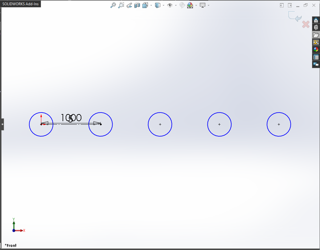
CASE 1 : Increase Total number of instances along the “X” axis
To increase Total number of instances along the “X” axis, we need to update NumX parameter in EditLinearSketchStepAndRepeat method.
In my previous Solidworks Macro - Linear Sketch Pattern post, we created a Linear pattern 3 instances in x-direction.
Code sample:
' Edit a Linear Sketch Pattern
BoolStatus = swSketchManager.EditLinearSketchStepAndRepeat(5, 1, 1, 0, 0, 0, "", True, False, True, True, False, "Arc1_")
In above code, we update the number of instances from 3 instances to 5 instances.
Example Images:
Below image shows before and after we update number of instance in X-direction.
Before Edit Linear Sketch Pattern
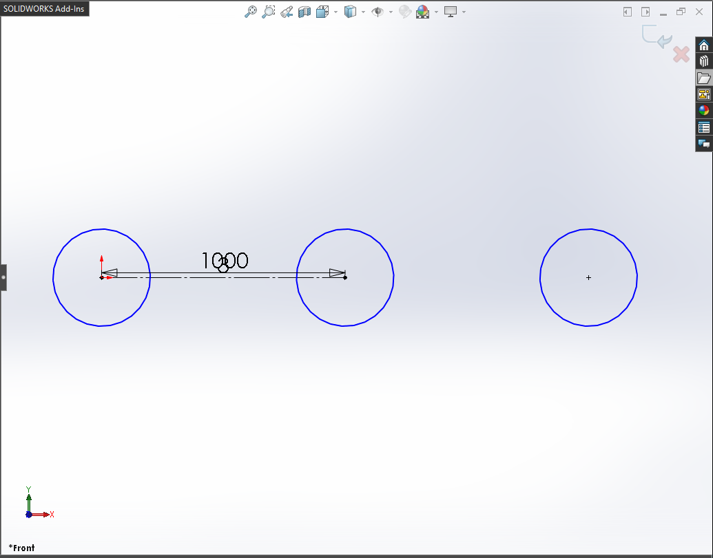
After Edit Linear Sketch Pattern
CASE 2 : Increase Total number of instances along the “Y” axis
To increase Total number of instances along the “Y” axis, we need to update NumY parameter in EditLinearSketchStepAndRepeat method.
If we increase the number of instances in Y-direction, then we also need to give value for SpacingY parameter.
We need following parameters to update:
-
NumY
-
SpacingY
We will use following values for these parameters:
-
NumY: 4
-
SpacingY: 0.75
Code sample:
' Edit a Linear Sketch Pattern
BoolStatus = swSketchManager.EditLinearSketchStepAndRepeat(5, 4, 1, 0.75, 0, 0, "", True, False, True, True, False, "Arc1_")
Example Images:
Below image shows before and after we update number of instance in Y-direction.
Before Edit Linear Sketch Pattern
After Edit Linear Sketch Pattern
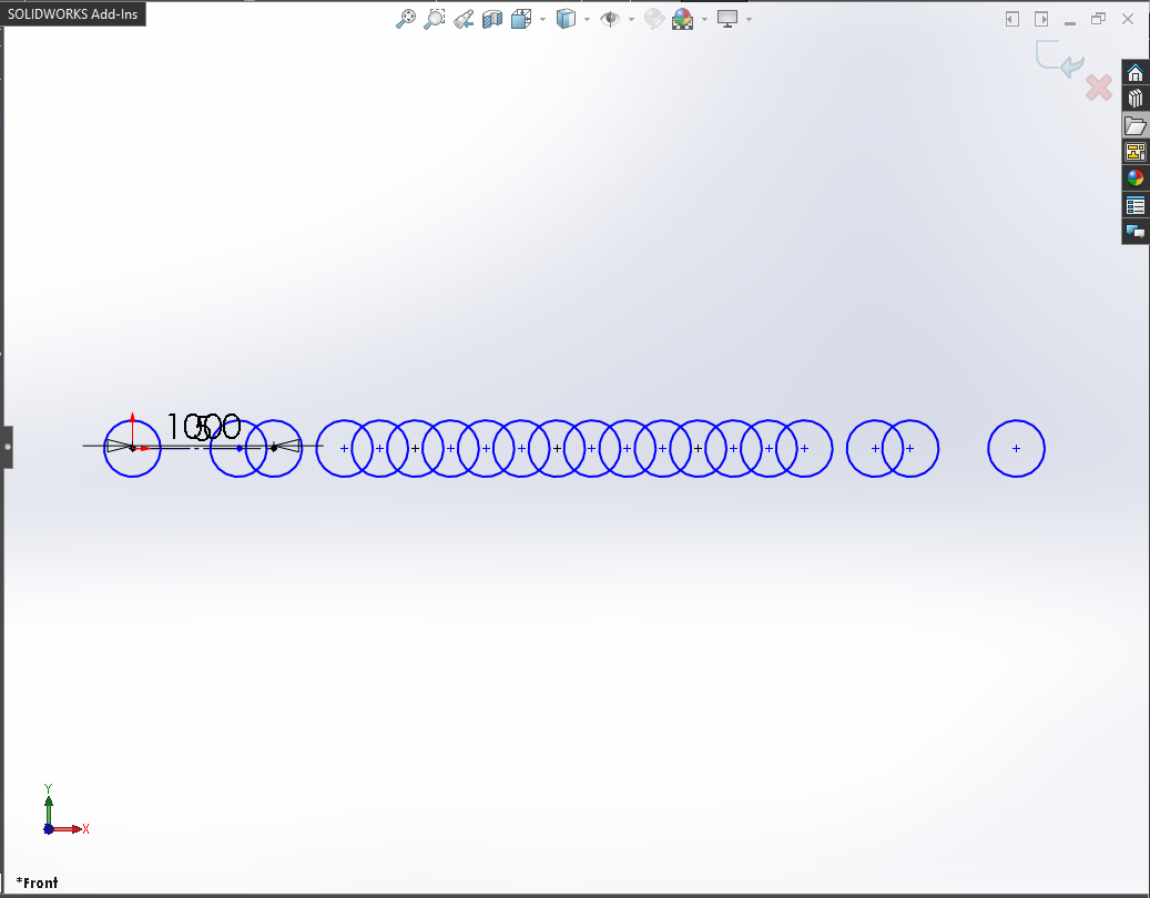
As you notice in previous image, when you give values for NumY and SpacingY, number of instances increased in X-direction!
Why the instances are increased in X-direction not in Y-direction as I was expecting?
This question comes in my mind after seeing the result!
Reason is that we did not give value of AngleY parameter.
If you provide the value of AngleY parameter then we can have instances in Y-direction.
More detail with example in CASE 4.
CASE 3 : Update Angle for direction 1 along the “X” axis
To update Angle for direction 1 along the “X” axis, we need to update AngleX parameter in EditLinearSketchStepAndRepeat method.
We will use following value for AngleX parameter:
- AngleX: 0.785.
Code sample:
' Edit a Linear Sketch Pattern
BoolStatus = swSketchManager.EditLinearSketchStepAndRepeat(5, 4, 1, 0.75, 0.785, 0, "", True, False, True, True, False, "Arc1_")
Example Images:
Below image shows before and after we update Angle for direction 1 along the “X” axis.
Before Edit Linear Sketch Pattern
After Edit Linear Sketch Pattern
In this case, we use AngleX = 0.785.
This value is in Radian.
Hence, 0.785 Radian = 44.999 Degree
So we have update Angle for direction 1 in ~45 degree.
CASE 4 : Update Angle for direction 1 along the “Y” axis
To update Angle for direction 2 along the “Y” axis, we need to update AngleY parameter in EditLinearSketchStepAndRepeat method.
We will use following value for AngleY parameter:
- AngleX: 1.5708.
Code sample:
' Edit a Linear Sketch Pattern
BoolStatus = swSketchManager.EditLinearSketchStepAndRepeat(5, 4, 1, 0.75, 0.785, 1.5708, "", True, False, True, True, False, "Arc1_")
Example Images:
Below image shows before and after we update Angle for direction 2 along the “Y” axis.
Before Edit Linear Sketch Pattern
After Edit Linear Sketch Pattern
In this case, we use AngleY = 1.5708.
This value is in Radian.
Hence, 1.5708 Radian = 90 Degree
So we have update Angle for direction 1 in 90 degree.
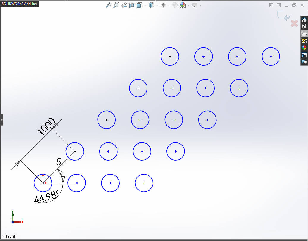
CASE 5 : Number of instances to delete
Ok, this one is a little “tricky”!!!
We want to delete some instance now.
For deleting instances, we need following:
-
Deleting instance’s position with respect to X and Y directions.
-
Those position in a particular format.
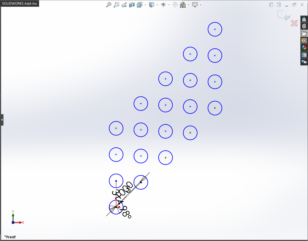
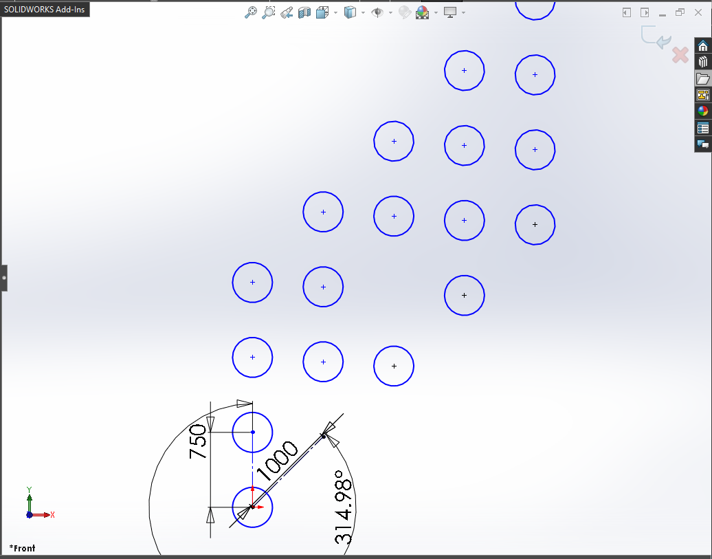
Grid Position Image:
I tried my best to describe you this position system in Grid format using image.
Please see below image for this Grid position.
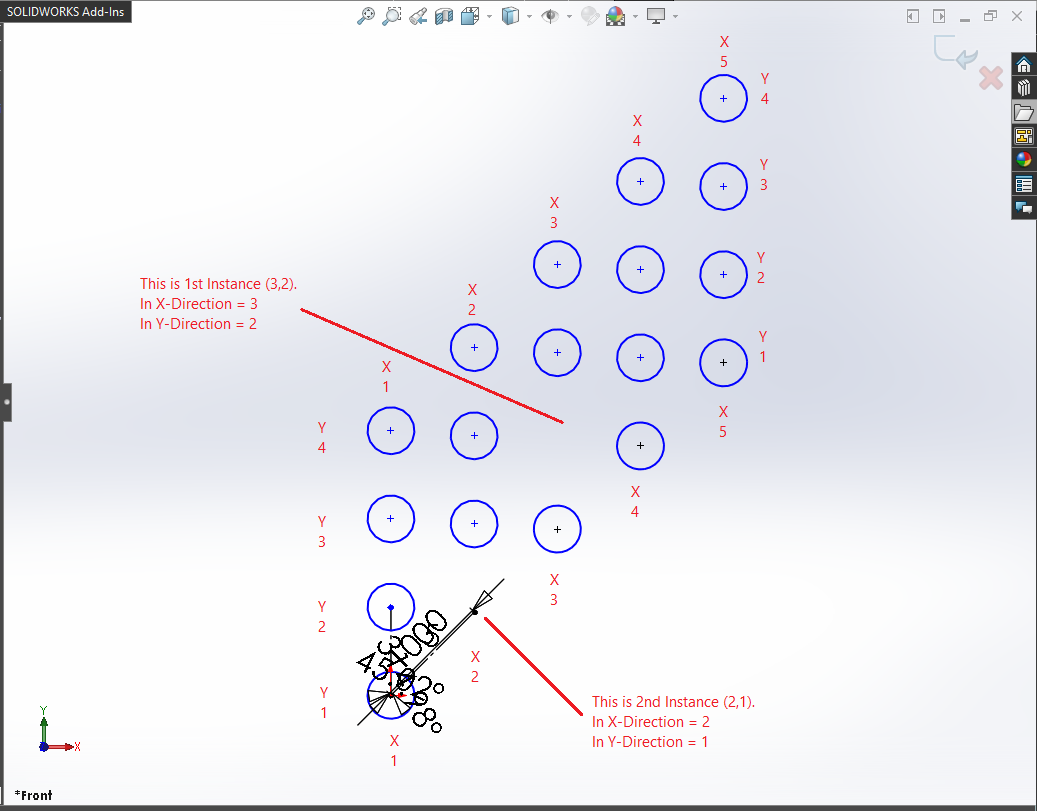
We are going to delete 2 instances.
1st Instance: First we will get the position of this instance.
-
In X-Direction: As you can see in above image, position of this instance is 3 in Grid position system for X-Direction.
-
In Y-Direction: As you can see in above image, position of this instance is 2 in Grid position system for Y-Direction.
2nd Instance: First we will get the position of this instance.
-
In X-Direction: As you can see in above image, position of this instance is 2 in Grid position system for X-Direction.
-
In Y-Direction: As you can see in above image, position of this instance is 1 in Grid position system for Y-Direction.
Position in special format: After we get the position, we need to put “Grid position” of each instance inside a bracket (or paranthesis).
One thing to note here is that, there should be no “comma” between bracket (or paranthesis).
Please see below code sample for detail.
Code sample:
' Edit a Linear Sketch Pattern
BoolStatus = swSketchManager.EditLinearSketchStepAndRepeat(5, 4, 1, 0.75, 0.785, 1.5708, "(3,2)(2,1)", True, False, True, True, False, "Arc1_")
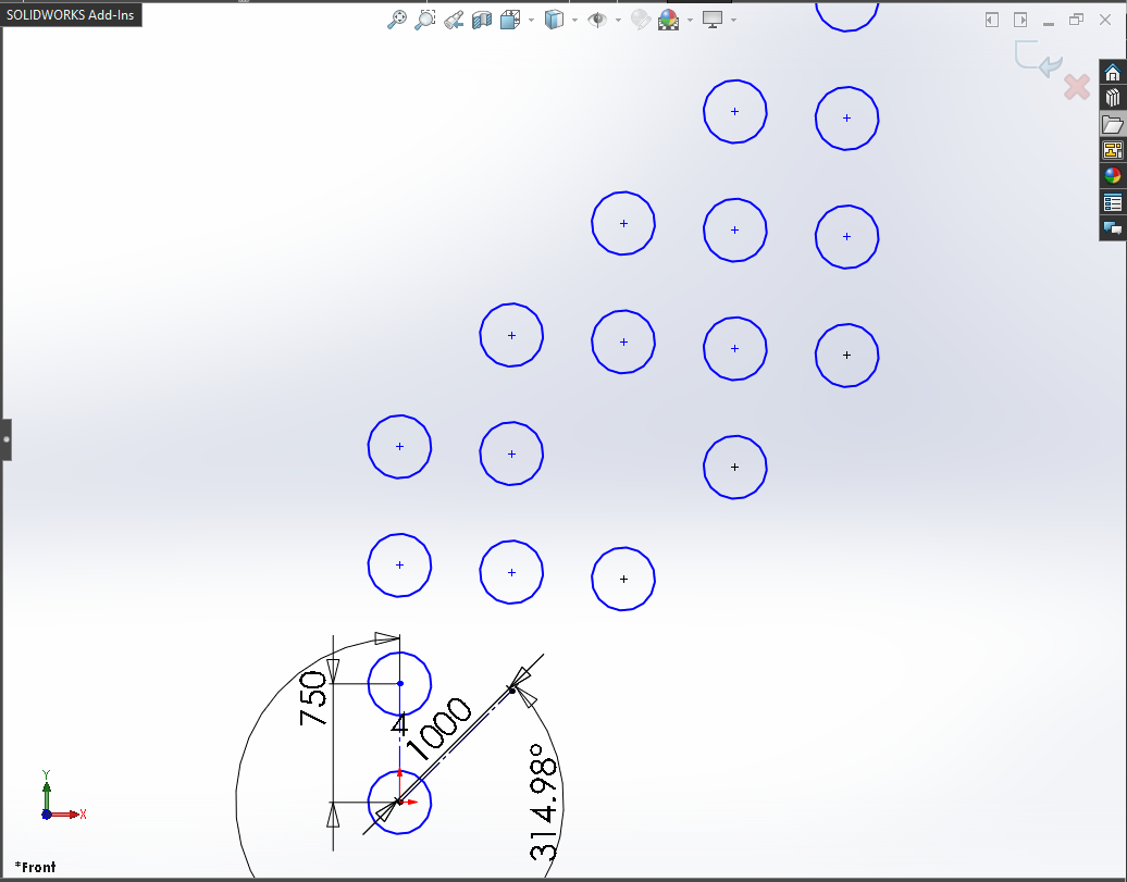
CASE 6 : Display the spacing between instances dimension along the “Y” axis
In our code sample, we display the spacing between instances dimension along the X axis.
We do this by XSpacingDim = True.
If we want to display the spacing between instances dimension along the Y axis.
For that we need to set YSpacingDim = True.
Code sample:
' Edit a Linear Sketch Pattern
BoolStatus = swSketchManager.EditLinearSketchStepAndRepeat(5, 4, 1, 0.75, 0.785, 1.5708, "(3,2)(2,1)", True, True, True, True, False, "Arc1_")
Example Images:
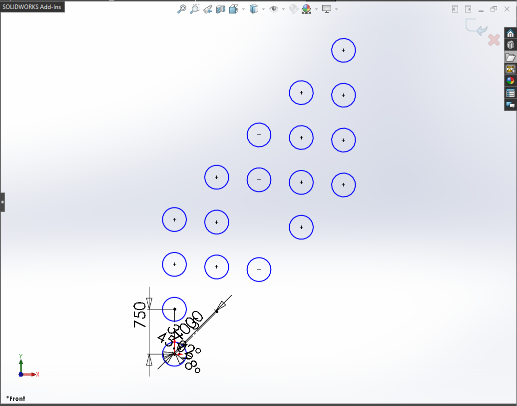
Below image shows after we update value for display dimension along the **Y axis**.
Before Edit Linear Sketch Pattern
CASE 7 : Display the angle dimension between axes
In our code sample, we display the angle dimension between axes.
We do this by AngleDim = True.
If we don’t want to display the angle dimension between axes then we need to set AngleDim = False.
Code sample:
' Edit a Linear Sketch Pattern
BoolStatus = swSketchManager.EditLinearSketchStepAndRepeat(5, 4, 1, 0.75, 0.785, 1.5708, "(3,2)(2,1)", True, True, False, True, False, "Arc1_")
Example Images:
Below image shows after we update value to False for the angle dimension between axes.
Before Edit Linear Sketch Pattern
CASE 8 : Display the number of instances in the “X” direction
In our code sample, we display the number of instances along the X axis.
We do this by CreateNumOfInstancesDimInXDir = True.
If we don’t want to display the number of instances along the X axis then we need to set CreateNumOfInstancesDimInXDir = False.
Code sample:
' Edit a Linear Sketch Pattern
BoolStatus = swSketchManager.EditLinearSketchStepAndRepeat(5, 4, 1, 0.75, 0.785, 1.5708, "(3,2)(2,1)", True, True, False, False, False, "Arc1_")
Example Images:
Below image shows after we update value to False for not display the number of instances in the X direction.
Before Edit Linear Sketch Pattern
CASE 9 : Display the number of instances in the “Y” direction
In our code sample, we don’t display the number of instances along the Y axis.
We do this by CreateNumOfInstancesDimInYDir = False.
If we want to display the number of instances along the Y axis then we need to set CreateNumOfInstancesDimInYDir = True.
Code sample:
' Edit a Linear Sketch Pattern
BoolStatus = swSketchManager.EditLinearSketchStepAndRepeat(5, 4, 1, 0.75, 0.785, 1.5708, "(3,2)(2,1)", True, True, False, False, True, "Arc1_")
Example Images:
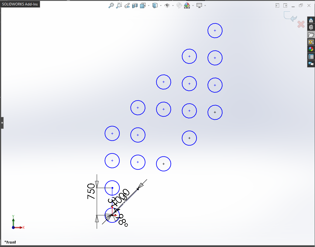
Below image shows after we update value to True for display the number of instances in the Y direction.
Before Edit Linear Sketch Pattern
CASE 10 : Multiple entities as Seed
In our code sample, we use only 1 circle for Linear Sketch pattern.
But in many cases we need to select many sketch entities.
In this condition, add the entities name with an underscore (_) one by one.
For example, we want to pattern a Ractangle, in this case, value of seed should be following:
- Seed :
Line1_Line2_Line3_Line4_
It is very important to remember that, when you give distance or any other numeric value in Solidworks API, Solidworks takes that numeric value in Meter only.
Please see below for detail:
- Length: Meter
- Angle: Radian
Solidworks API does not care about your application’s Unit systems.
For example, I works in ANSI system means inches for distance. But when I used Solidworks API through VBA macros or C#, I need to converted numeric values.
Because Solidworks API output the distance in Meter which is not my requirement.
This is it !!!
If you found anything to add or update, please let me know on my e-mail.
Hope this post helps you to Edit a Linear Sketch Pattern with Solidworks VBA Macros.
For more such tutorials on Solidworks VBA Macro, do come to this blog after sometime.
If you like the post then please share it with your friends also.
Do let me know by you like this post or not!
Till then, Happy learning!!!