Solidworks Macro - Linear Sketch Pattern
In this post, I tell you about how to Linear Sketch Pattern using Solidworks VBA Macros in a Sketch.
Video of Code on YouTube
Please see below video how visually we Linear Sketch Pattern in Solidworks VBA macro.
Please note that there are no explaination in the video.
Explaination of each line and why we write code this way is given in this post.
For Experience Macro Developers
If you are an experience Solidworks Macro developer, then you are looking for a specific code sample.
Below is the code for Linear Sketch Pattern from Solidworks VBA Macro.
' Boolean Variable
Dim BoolStatus As Boolean

' Select Circle we want to Pattern
BoolStatus = swDoc.Extension.SelectByID2("Arc1", "SKETCHSEGMENT", 0, 0, 0, True, 1, Nothing, swSelectOption_e.swSelectOptionDefault)

' Create a Linear Sketch Pattern
BoolStatus = swSketchManager.CreateLinearSketchStepAndRepeat(1, 3, 1, 1, 0, 1.57, "", False, True, True, False, True)
Method Name: CreateLinearSketchStepAndRepeat
Description: Create Linear Sketch Pattern of the selected sketch entity or entities.
Prerequisites: To create a Linear Sketch Pattern a Solidworks Sketch entity or entities, first we need following things:
-
Sketch Entity/Entities to Pattern
-
That Entity/Entities is selected before pattern
How it works:
-
For Linear Sketch Pattern, first you need to Create a variable of
Booleantype. -
After creating variable, you need to set the value of this
Booleanvariable. -
For this you used
CreateLinearSketchStepAndRepeatmethod from Solidworks Sketch Manager. -
This
CreateLinearSketchStepAndRepeatmethod set the value ofBooleantype variable. -
If the Linear Sketch Pattern is successful then
CreateLinearSketchStepAndRepeatmethod return True value otherwiseCreateLinearSketchStepAndRepeatreturns False value.
This CreateLinearSketchStepAndRepeat method takes following parameters as explained:
-
NumX : Total number of instances along the x axis, including the seed i.e. original entity/entities.
-
NumY : Total number of instances along the y axis, including the seed i.e. original entity/entities.
-
SpacingX : Spacing between instances along the x axis.
-
SpacingY : Spacing between instances along the y axis.
-
AngleX : Angle for direction 1 relative to the x axis.
-
AngleY : Angle for direction 1 relative to the y axis.
-
DeleteInstances : Number of instances to delete, passed as a string in the format: “(a) (b) (c)”.
-
XSpacingDim : True to display the spacing between instances dimension along the x axis in the graphics area, false to not
-
YSpacingDim : True to display the spacing between instances dimension along the y axis in the graphics area, false to not
-
AngleDim : True to display the angle dimension between axes in the graphics area, false to not.
-
CreateNumOfInstancesDimInXDir : True to display the number of instances in the x direction dimension in the graphics area, false to not.
-
CreateNumOfInstancesDimInYDir : True to display the number of instances in the y direction dimension in the graphics area, false to not.
If you want more detailed explaination then please read further otherwise this will help you to create a Linear Sketch Pattern.
For Beginner Macro Developers
In this post, I tell you about CreateLinearSketchStepAndRepeat method from Solidworks SketchManager object.
This method is most updated method, I found in Solidworks API Help.
So use this method if you want to create Linear Sketch Pattern.
Below is the code sample to create Linear Sketch Pattern.
Option Explicit

' Create variable for Solidworks application
Dim swApp As SldWorks.SldWorks

' Create variable for Solidworks document
Dim swDoc As SldWorks.ModelDoc2

' Boolean Variable
Dim BoolStatus As Boolean

' Create variable for Solidworks Sketch Manager
Dim swSketchManager As SldWorks.SketchManager

' Create Variable for Solidworks Sketch Segment
Dim swSketchSegment As SldWorks.SketchSegment

' Main function of our VBA program
Sub main()

  ' Set Solidworks variable to Solidworks application
  Set swApp = Application.SldWorks

  ' Create string type variable for storing default part location
  Dim defaultTemplate As String

  ' Set value of this string type variable to "Default part template"
  defaultTemplate = swApp.GetUserPreferenceStringValue(swUserPreferenceStringValue_e.swDefaultTemplatePart)

  ' Set Solidworks document to new part document
  Set swDoc = swApp.NewDocument(defaultTemplate, 0, 0, 0)

  ' Select Front Plane
  BoolStatus = swDoc.Extension.SelectByID2("Front Plane", "PLANE", 0, 0, 0, False, 0, Nothing, swSelectOption_e.swSelectOptionDefault)

  ' Set Sketch manager for our sketch
  Set swSketchManager = swDoc.SketchManager

  ' Insert a sketch into selected plane
  swSketchManager.InsertSketch True

  ' Set Sketch Segment value and Create a Circle
  Set swSketchSegment = swSketchManager.CreateCircleByRadius(0, 0, 0, 0.2)

  ' De-select the lines after creation
  swDoc.ClearSelection2 True

  ' Select Circle we want to Pattern
  BoolStatus = swDoc.Extension.SelectByID2("Arc1", "SKETCHSEGMENT", 0, 0, 0, True, 1, Nothing, swSelectOption_e.swSelectOptionDefault)

  ' Create a Linear Sketch Pattern
  BoolStatus = swSketchManager.CreateLinearSketchStepAndRepeat(3, 1, 1, 0, 0, 0, "", True, False, True, True, False)

  ' De-select the Sketch Segment after Linear Sketch Pattern
  swDoc.ClearSelection2 True

  ' Show Front View after Linear Sketch Pattern
  swDoc.ShowNamedView2 "", swStandardViews_e.swFrontView

  ' Zoom to fit screen in Solidworks Window
  swDoc.ViewZoomtofit2

End Sub
Understanding the Code
Now let us walk through each line in the above code, and understand the meaning and purpose of every line.
I also give some link so that you can go through them if there are anything I explained in previous posts.
Option Explicit
This line forces us to define every variable we are going to use.
For more information please visit Solidworks Macros - Open new Part document post.
' Create variable for Solidworks application
Dim swApp As SldWorks.SldWorks
In this line, we create a variable which we named as swApp and the type of this swApp variable is SldWorks.SldWorks.
' Create variable for Solidworks document
Dim swDoc As SldWorks.ModelDoc2
In this line, we create a variable which we named as swDoc and the type of this swDoc variable is SldWorks.ModelDoc2.
' Boolean Variable
Dim BoolStatus As Boolean
In this line, we create a variable named BoolStatus as Boolean object type.
' Create variable for Solidworks Sketch Manager
Dim swSketchManager As SldWorks.SketchManager
In above line, we create variable swSketchManager for Solidworks Sketch Manager.
As the name suggested, a Sketch Manager holds variours methods and properties to manage Sketches.
To see methods and properties related to SketchManager object, please visit this page of Solidworks API Help
' Create variable for Solidworks Sketch Segment
Dim swSketchSegment As SldWorks.SketchSegment
In this line, we Create a variable which we named as swSketchSegment and the type of this swSketchSegment variable is SldWorks.SketchSegment.
We create variable swSketchSegment for Solidworks Sketch Segments.
To see methods and properties related to swSketchSegment object, please visit this page of Solidworks API Help
These all are our global variables.
As you can see in code sample, they are Solidworks API Objects.
So basically I group all the Solidworks API Objects in one place.
I have also place boolean type object at top also, because after certain point we will need this variable frequently.
Thus, I have started placing it here.
Next is our Sub procedure which has name of main.
This procedure hold all the statements (instructions) we give to computer.
' Set Solidworks variable to Solidworks application
Set swApp = Application.SldWorks
In this line, we set the value of our Solidworks variable swApp; which we define earlier; to Solidworks application.
' Create string type variable for storing default part location
Dim defaultTemplate As String
' Set value of this string type variable to "Default part template"
defaultTemplate = swApp.GetUserPreferenceStringValue(swUserPreferenceStringValue_e.swDefaultTemplatePart)
In 1st statement of above example, we are defining a variable of string type and named it as defaultTemplate.
This variable defaultTemplate, hold the location the location of Default Part Template.
In 2nd line of above example. we assign value to our newly define defaultTemplate variable.
We assign the value by using a Method named GetUserPreferenceStringValue().
This GetUserPreferenceStringValue() method is a part of our main Solidworks variable swApp.
' Set Solidworks document to new part document
Set swDoc = swApp.NewDocument(defaultTemplate, 0, 0, 0)
In this line, we set the value of our swDoc variable to new document.
For detailed information about these lines please visit Solidworks Macros - Open new Part document post.
I have discussed them thoroghly in Solidworks Macros - Open new Part document post, so do checkout that post if you want to understand above code in more detail.
' Select Front Plane
BoolStatus = swDoc.Extension.SelectByID2("Front Plane", "PLANE", 0, 0, 0, False, 0, Nothing, swSelectOption_e.swSelectOptionDefault)
In above line, we select the front plane by using SelectByID2 method from Extension object.
For more information about selection method please visit Solidworks Macros - Selection Methods post.
' Set Sketch manager for our sketch
Set swSketchManager = swDoc.SketchManager
In above line, we set the Sketch manager variable to current document’s sketch manager.
' Insert a sketch into selected plane
swSketchManager.InsertSketch True
In above line, we use InsertSketch method of SketchManager and give True value.
This method allows us to insert a sketch in selected plane.
' Set Sketch Segment value and Create a Circle
Set swSketchSegment = swSketchManager.CreateCircleByRadius(0, 0, 0, 0.2)
In above line, we set the value of Solidworks Sketch Segment variable swSketchSegment by CreateCircleByRadius method from Solidworks Sketch Manager.
This CreateCircleByRadius method creates a Circle at given point with radius.
For more information about CreateCircleByRadius method, you can read my Solidworks Macro - Create Circle By Radius post.
That post describe all the parameters we need for this CreateCircleByRadius method in details.
In above line, we create a Circle with:
-
Circle Centerpoint : At origin i.e. (0, 0, 0)
-
Circle Radius : 0.2
' De-select the lines after creation
swDoc.ClearSelection2 True
After creating the circle we de-select it.
We don’t need to de-select the circle for Pattern as we will select the circle agains in next line. I just want to show you how to select a Sketch Segment with
SelectByIdMenthod in next line of code.
' Select Circle we want to Pattern
BoolStatus = swDoc.Extension.SelectByID2("Arc1", "SKETCHSEGMENT", 0, 0, 0, True, 0, Nothing, swSelectOption_e.swSelectOptionDefault)
In above line of code, we select the Circle i.e. Arc 1 and add it to selection list.
' Create a Linear Sketch Pattern
BoolStatus = swSketchManager.CreateLinearSketchStepAndRepeat(3, 1, 1, 0, 0, 0, "", True, False, True, True, False)
In above line, we Pattern selected Circle by CreateLinearSketchStepAndRepeat method from Solidworks Sketch Manger variable.
This CreateLinearSketchStepAndRepeat method takes following parameters as explained:
-
NumX : Total number of instances along the x axis, including the seed i.e. original entity/entities.
-
NumY : Total number of instances along the y axis, including the seed i.e. original entity/entities.
-
SpacingX : Spacing between instances along the x axis.
-
SpacingY : Spacing between instances along the y axis.
-
AngleX : Angle for direction 1 relative to the x axis.
-
AngleY : Angle for direction 1 relative to the y axis.
-
DeleteInstances : Number of instances to delete, passed as a string in the format: “(a) (b) (c)”.
-
XSpacingDim : True to display the spacing between instances dimension along the x axis in the graphics area, false to not
-
YSpacingDim : True to display the spacing between instances dimension along the y axis in the graphics area, false to not
-
AngleDim : True to display the angle dimension between axes in the graphics area, false to not.
-
CreateNumOfInstancesDimInXDir : True to display the number of instances in the x direction dimension in the graphics area, false to not.
-
CreateNumOfInstancesDimInYDir : True to display the number of instances in the y direction dimension in the graphics area, false to not.
After the function complete following are the results:
Return Value:
-
True: If Linear Sketch Pattern is *Success.*
-
False: If Linear Sketch Pattern is *Fail.*
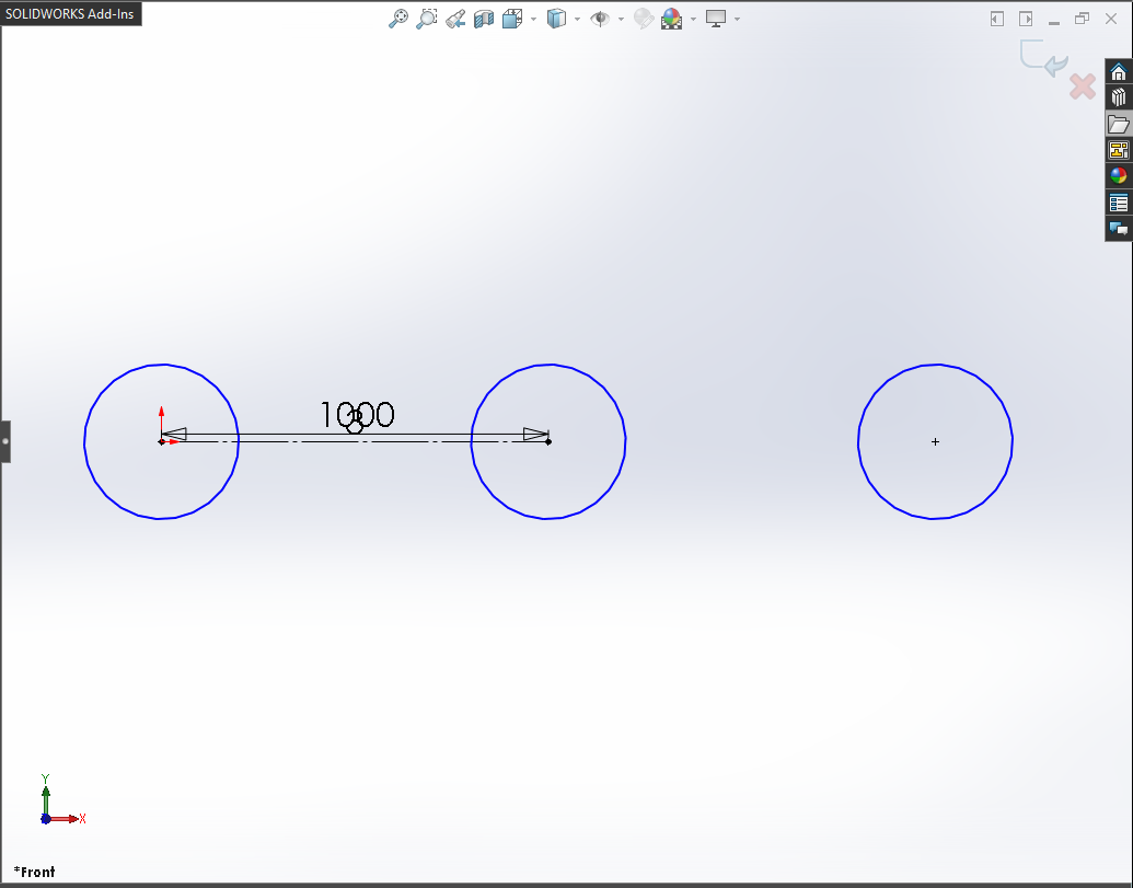
In our code, I have used following values:
-
NumX : I have used 3 as Total number of instances along the x axis including original circle.
-
NumY : I have used 1 as Total number of instances along the y axis which includes original circle only.
Even uf you don’t want to pattern in Y direction, you have to give atleast 1 as a value. Same goes for X direction.
-
SpacingX : I use 1 as Spacing between instances along the x axis.
-
SpacingY : I use 0 Spacing between instances along the y axis.
-
AngleX : I use 0 Angle for direction 1 relative to the x axis.
-
AngleY : I use 0 Angle for direction 1 relative to the y axis.
-
DeleteInstances : I use ”“ as Number of instances to delete, because I don’t want to delete any instances.
-
XSpacingDim : I use True to display the spacing between instances dimension along the x axis in the graphics area.
-
YSpacingDim : I use False to display the spacing between instances dimension along the y axis in the graphics area.
-
AngleDim : I use True to display the angle dimension between axes in the graphics area.
-
CreateNumOfInstancesDimInXDir : I use True to display the number of instances in the x direction dimension in the graphics area.
-
CreateNumOfInstancesDimInYDir : I use False to display the number of instances in the y direction dimension in the graphics area.
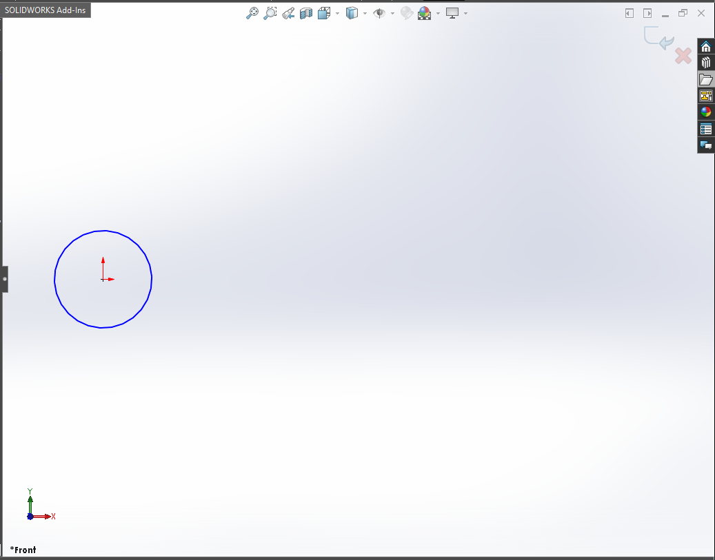
Below image shows before and after Linear Sketch Pattern.
Before Linear Sketch Pattern
After Linear Sketch Pattern
NOTE
It is very important to remember that, when you give distance or any other numeric value in Solidworks API, Solidworks takes that numeric value in Meter only.
Please see below for detail:
-
Length: Meter
-
Angle: Radian
Solidworks API does not care about your application’s Unit systems.
For example, I works in ANSI system means inches for distance. But when I used Solidworks API through VBA macros or C#, I need to converted numeric values.
Because Solidworks API output the distance in Meter which is not my requirement.
' De-select the Sketch after creation
swDoc.ClearSelection2 True
In the above line of code, we deselect the Sketch after the Linear Sketch Pattern operation.
For de-selecting, we use ClearSelection2 method from our Solidworks document name swDoc.
' Show Front View after Linear Sketch Pattern
swDoc.ShowNamedView2 "", swStandardViews_e.swFrontView
In the above line of code, we update the view orientation to Front View.
In my machine, after inserting a sketch view orientation does not changed.
Because of this I have to update the view to Front view.
For showing Front View we used ShowNamedView2 method from our Solidworks document name swDoc.
This method takes 2 parameter described as follows:
-
VName : Name of the view to display or an empty string to use ViewId instead
-
ViewId : ID of the view to display as defined by
swStandardViews_eor -1 to use the VName argument instead.
NOTE: If you specify both VName and ViewId, then ViewId takes precedence if the two arguments do not resolve to the same view.
swStandardViews_e has following Standard View Types:
-
swBackView
-
swBottomView
-
swDimetricView
-
swFrontView
-
swIsometricView
-
swLeftView
-
swRightView
-
swTopView
-
swExtendetricView
In our code, we did not use VName instead I used empty string in form of ”“ symbol.
I used ViewId value to specify view and used swStandardViews_e.swFrontView value to use Standard Front View.
' Zoom to fit screen in Solidworks Window
swDoc.ViewZoomtofit
In this last line we use zoom to fit command.
For Zoom to fit, we use ViewZoomtofit method from our Solidworks document variable swDoc.
This is it !!!
If you found anything to add or update, please let me know on my e-mail.
VBA Language feature used in this post
In this post used some features of VBA programming language.
This section of post, has some brief information about the VBA programming language specific features.
-
We use Option Explicit for capturing un-declared variables. If you want to read more about Option Explicit then please visit Declaring and Scoping of Variables.
-
Then we create variable for different data types. If you know in detail about the Variables, then please visit Variables and Data-types posts of this blog. It will help you to understand what Variables are and how to use them.
-
Then we create main Sub procedure for our macro. If you know in detail about the Sub procedure, then I suggest you to visit VBA Sub and Function Procedures and Executing Sub and Function Procedures posts of this blog. It will help you to understand what Procedures are and how to use them.
-
In most part we create some variables and set their values. We set those values by using some functions provided from objects. If you don’t know about the functions, then you should visit VBA Functions and VBA Functions that do more posts of this blog. It will help you to understand what functions are and how to use them.
Solidworks API Objects
In this post of Linear Sketch Pattern, we use Solidworks API objects and their methods.
This section contains the list of all Solidworks Objects used in this post.
I have also attached links of these Solidworks API Objects in API Help website.
If you want to explore those objects, you can use these links.
These Solidworks API Objects are listed below:
-
Solidworks Application Object
If you want explore Properties and Methods/Functions of Solidworks Application Object object you can visit this link.
-
Solidworks Document Object
If you want explore Properties and Methods/Functions of Solidworks Document Object object you can visit this link.
-
Solidworks Sketch Manager Object
If you want explore Properties and Methods/Functions of Solidworks Sketch Manager Object you can visit this link.
-
Solidworks Sketch Segment Object
If you want explore Properties and Methods/Functions of Solidworks Sketch Segment Object you can visit this link.
Hope this post helps you to Create Linear Sketch Pattern with Solidworks VBA Macros.
For more such tutorials on Solidworks VBA Macro, do come to this blog after sometime.
If you like the post then please share it with your friends also.
Do let me know by you like this post or not!
Till then, Happy learning!